Data East Jurassic Park Pinball
Repairs, Restorations, Tweaks and Insights

Introduction
October 6, 2017 (Updated May 2, 2022)
Data East's Jurassic Park is a pinball machine I've been interested in owning for over 15 years. Now I have one!
Data East's Jurassic Park pinball is based on the original 1993 film. Here are a few items that make Data East's Jurassic Park awesome.
- The pin integrates the theme very well and has a great playfield layout
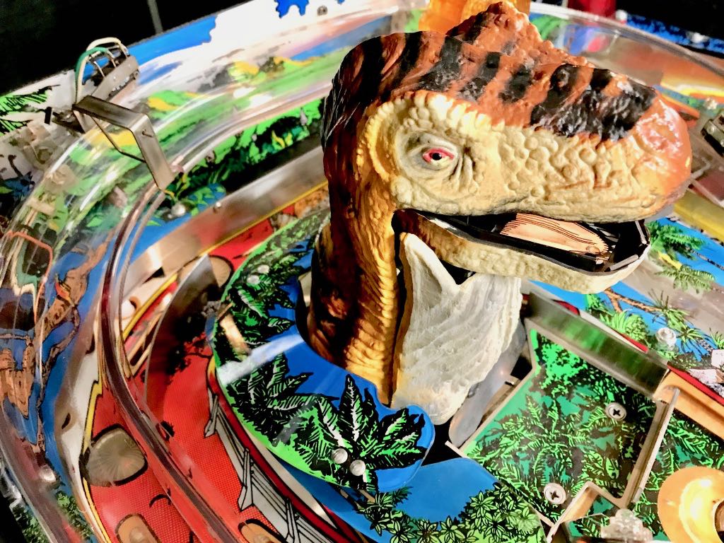
- The mechanical T-Rex moves from side to side and EATS THE PINBALL
- There are several modes, all of which are fun to play
Oh. Did I mention the T-Rex that eats pinballs? That is truly awesome.
Installing ColorDMD LED on Jurassic Park
May 2, 2022
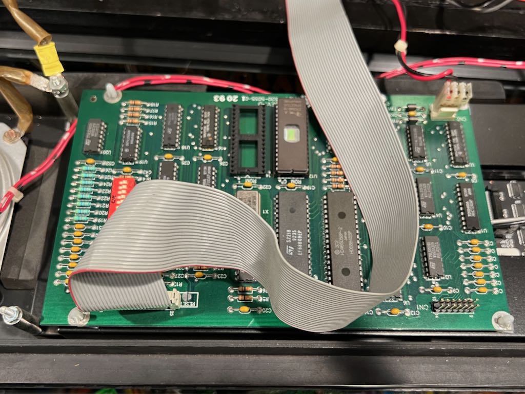
Start by making sure your Jurassic Park is powered off. Remove the backglass and place the speaker panel on the playfield as shown below. Unlike Williams pinball machines, the speaker panel includes a DMD logic board. As part of the installation, this logic board will need to be removed and attached to the ColorDMD LED board.
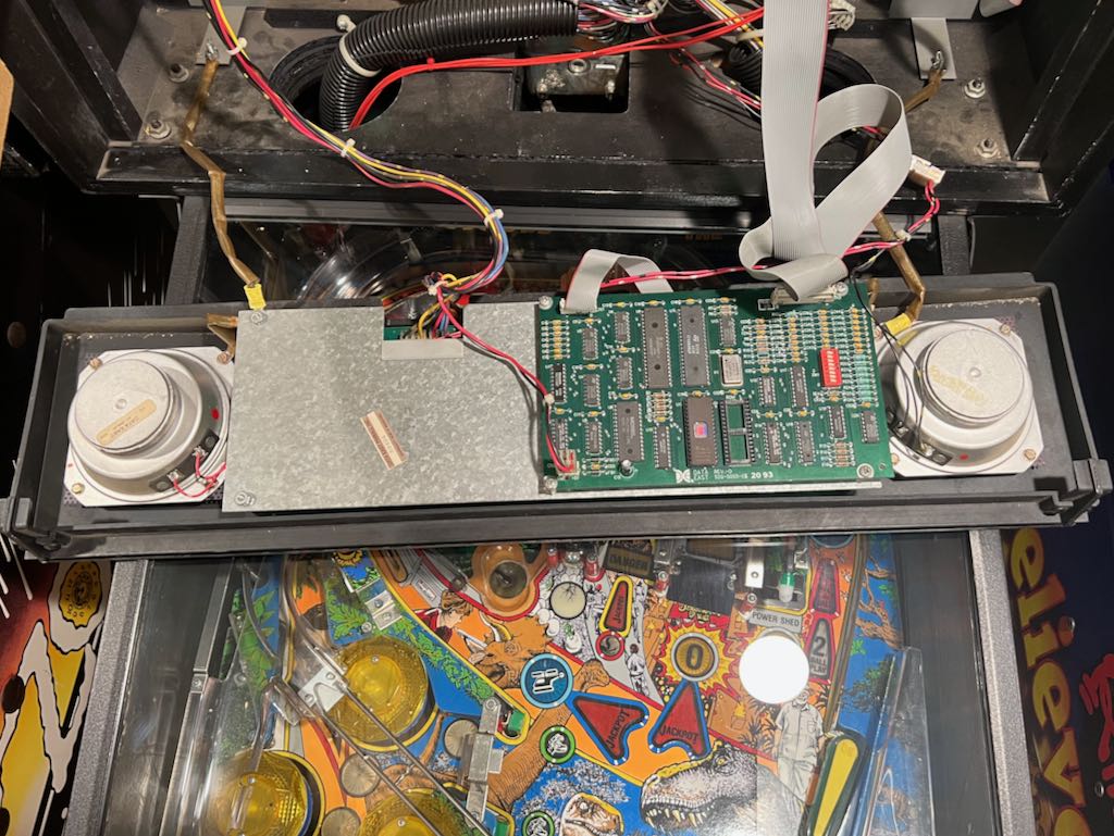
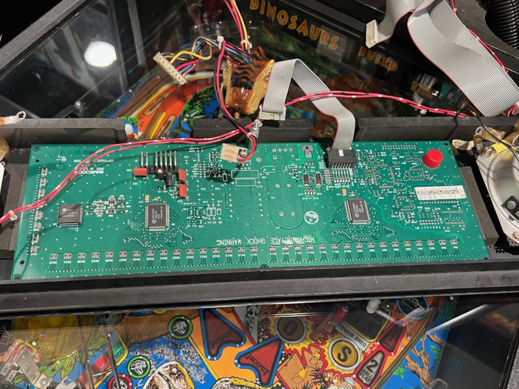
The DMD logic board is held in place by 4 screws, one on each corner. Remove the 4 screws and disconnect the 2 ribbon cables and 1 power cable attached to the DMD logic board. Spend a moment looking at these 3 connections because 2 of the 3 will need to be reconnected later (and a new cable will be used for the 3rd). The power cable at CN2 and the data ribbon cable at CN3 will be reused.
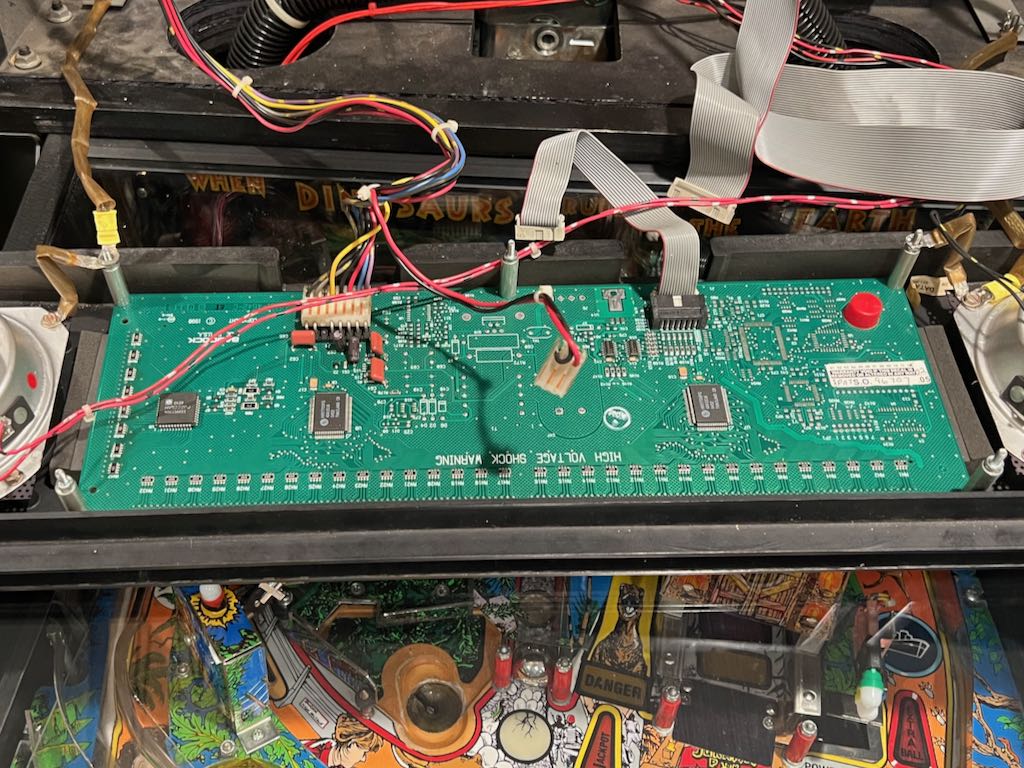
The image below shows the board removed. You can see it was supported by 4 metal posts. A 2nd picture shows the DMD logic board removed from mounting.
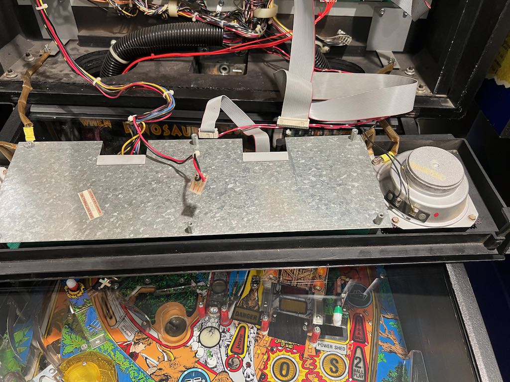
Now remove 3 of the 4 metal posts that previously supported the DMD logic board. In the picture below you can see the 3 that were removed on the top left, top right and bottom right. The 4th is permanently attached (bottom left).
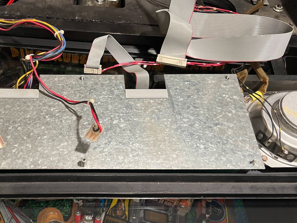
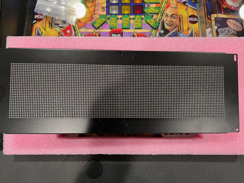
The metal plate can now be removed. Lift up on the plate to remove it from the posts. It may be a little sticky. The back of the DMD display will now be exposed (shown below).
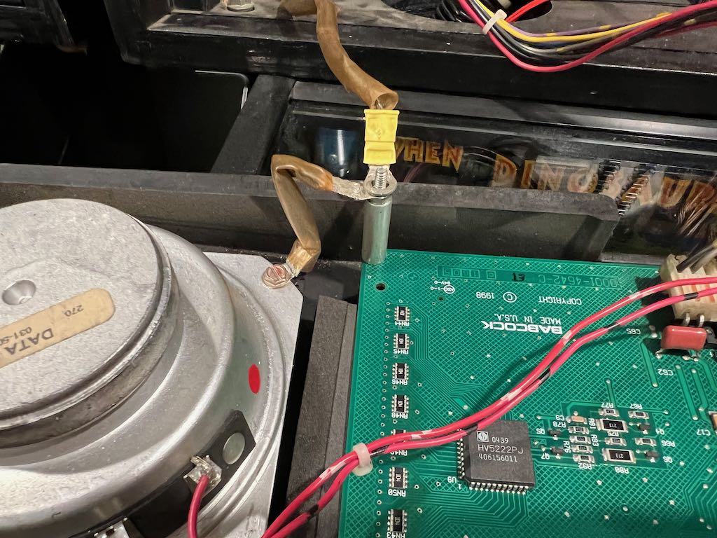
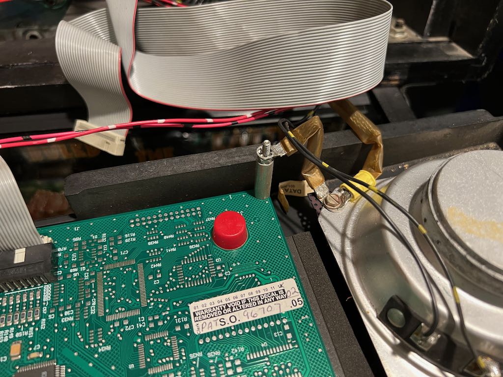
Take notice of the upper left and right posts and how the ground connectors are attached. You will need to reconnect these when installing the LED ColorDMD board. The two pictures below show the ground straps.
Remove the high voltage power cable (on the left) as well as the 4 metal posts at each corner of the DMD display. The results are shown below. You do not need to remove the ribbon cable on the right.
Lift out the DMD display and put it aside. This might be a little sticky but will come out with only a little force.
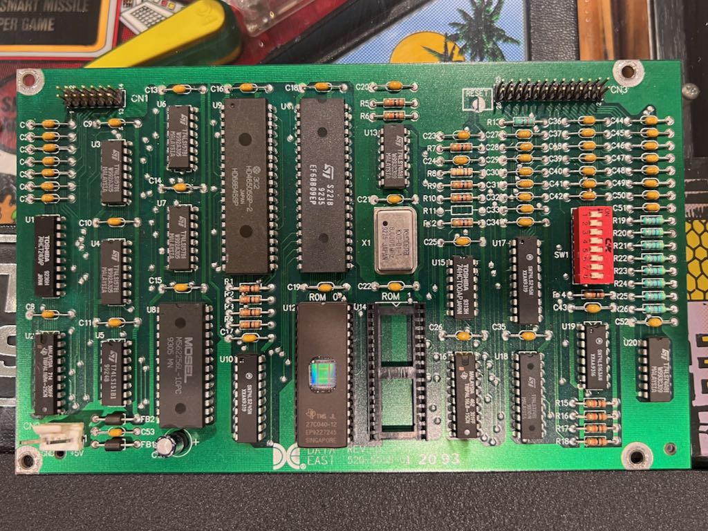
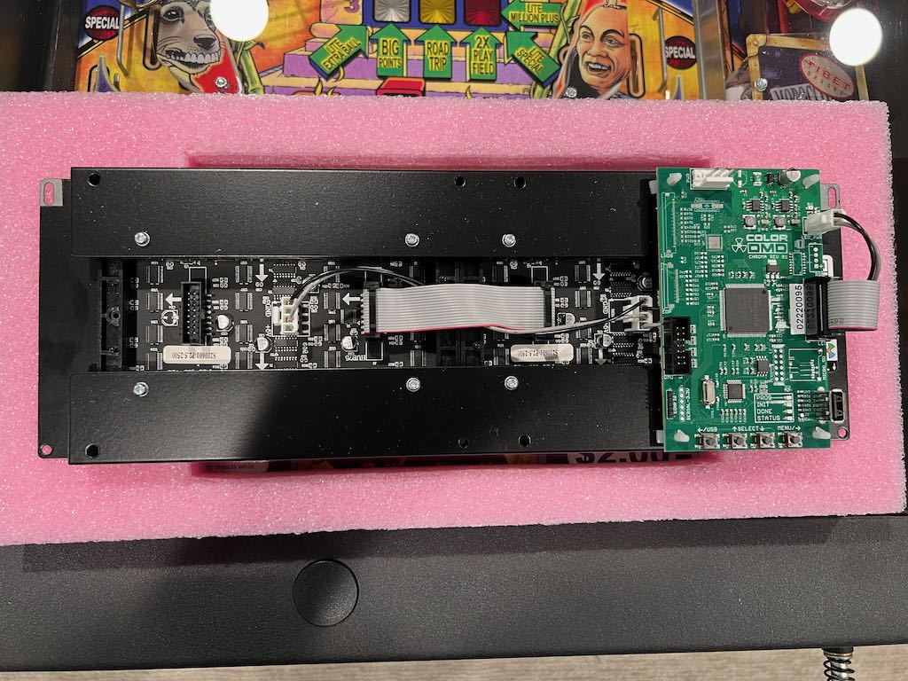
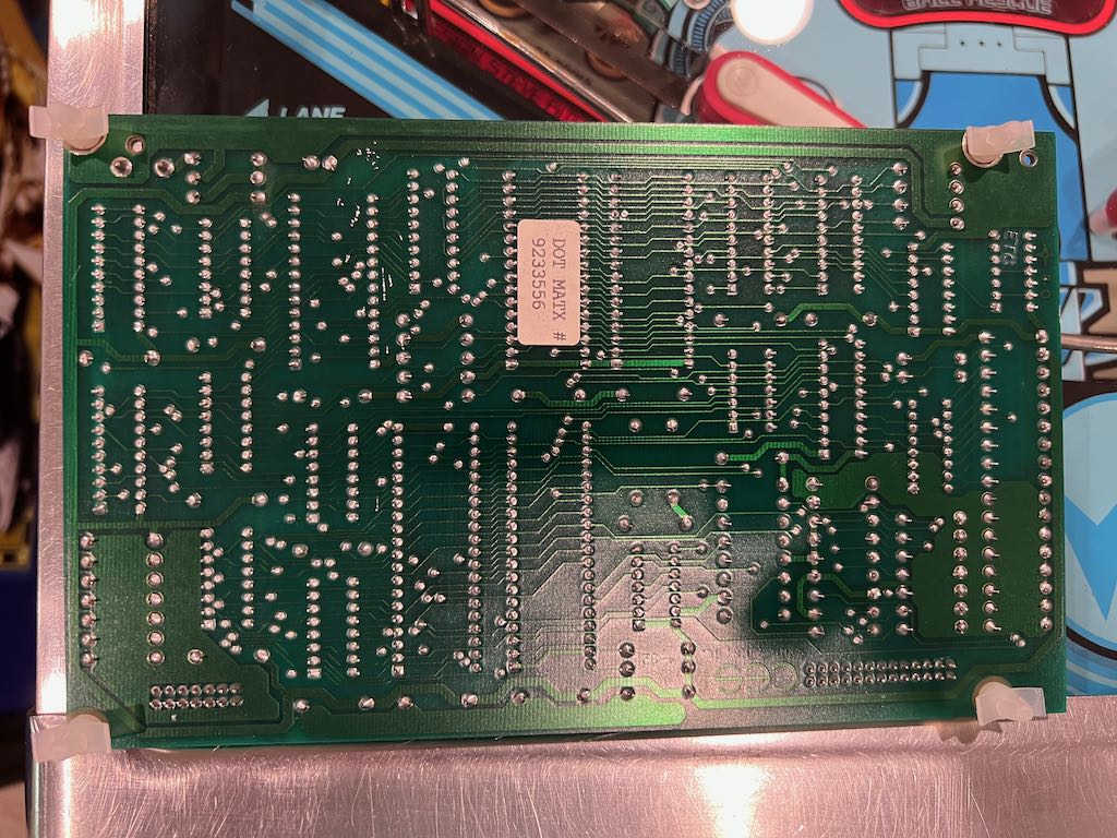
Now the DMD logic board, which we removed above, needs to be attached to the ColorDMD LED. For completeness, below is a picture of the front of the ColorDMD LED. There is also a picture of the back of the ColorDMD LED, where the original DMD logic board will be attached. The DMD logic board will mount on the back of the ColorDMD LED board using mounting holes and plastic spacers.
Using the plastic spacers included with the ColorDMD LED, attach one to each corner of the DMD logic board. This is shown in the two pictures below.
Now attach the DMD logic board to the back of the ColorDMD LED by pressing the 4 plastic spacers into the matching holes on the LED ColorDMD board.
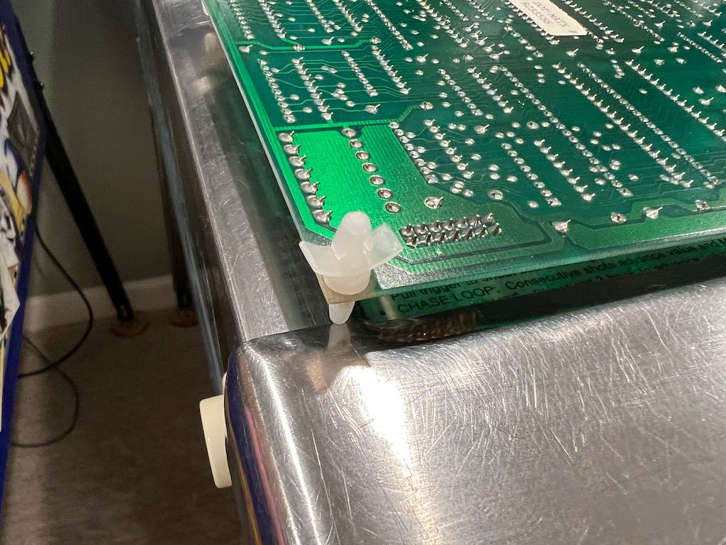
Attach the ColorDMD LED to the speaker panel using the posts and nuts that were previously removed. Make sure the upper left and upper right posts have the grounding wires attached. A picture of the upper left post is below.
The various connectors now need to be attached. The ColorDMD LED kit for Data East comes with an adaptor that enables powering the ColorDMD LED. This looks like a strange extender card with a connector in the middle.
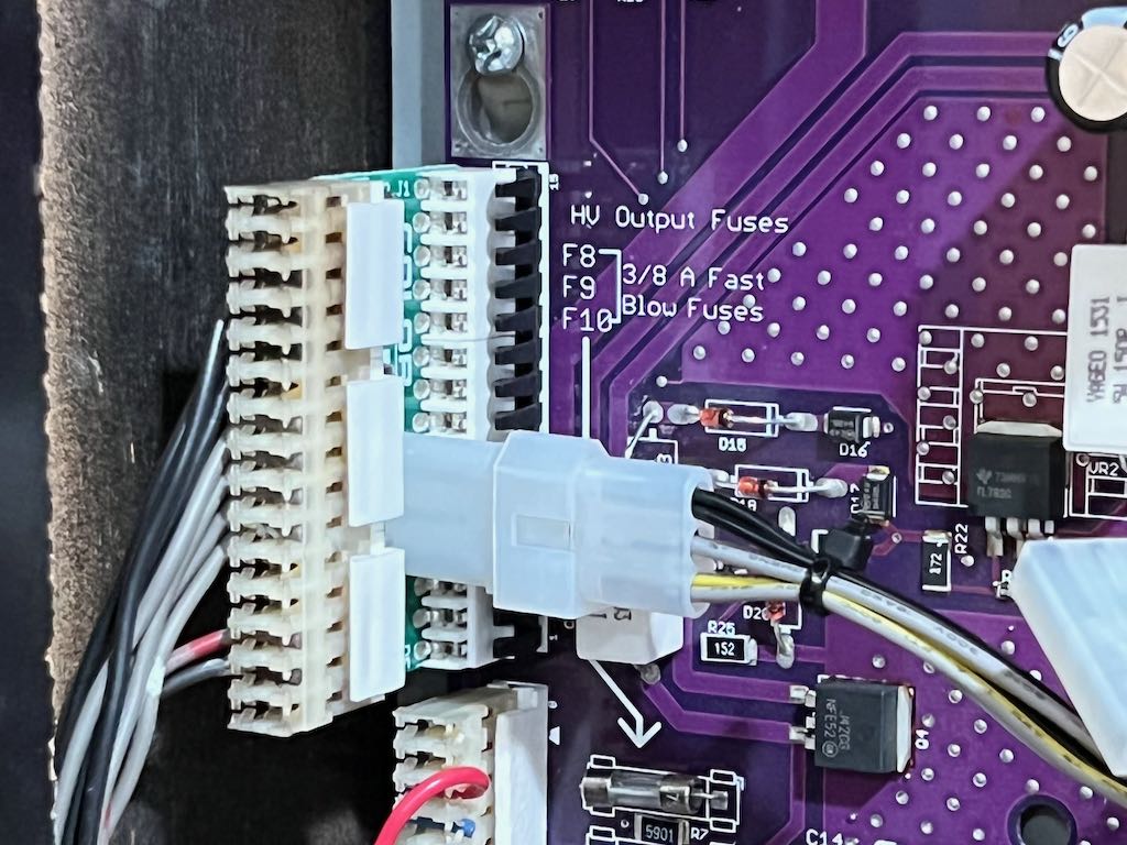
Remove the 15 pin connector on Jurassic Park's power board and insert this adaptor. Then connect the original 15 pin connector to the extender board as well as ColorDMD LED power cable.
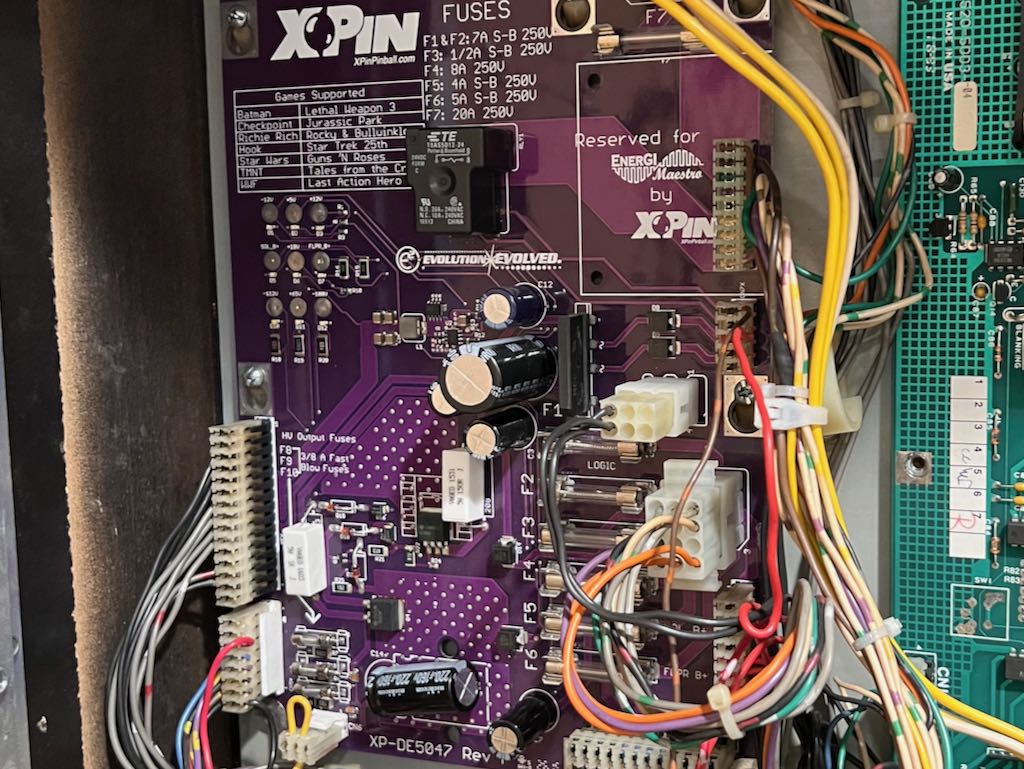
The first picture below shows the location of the power board's 15 pin connector (large connector on the left) followed by the installed adaptor. Note that I (unfortunately) do not have an original Data East power board.
Connect the other end of the ColorDMD power cable to the connector labeled "PWR" on the ColorDMD LED board. This is shown below.
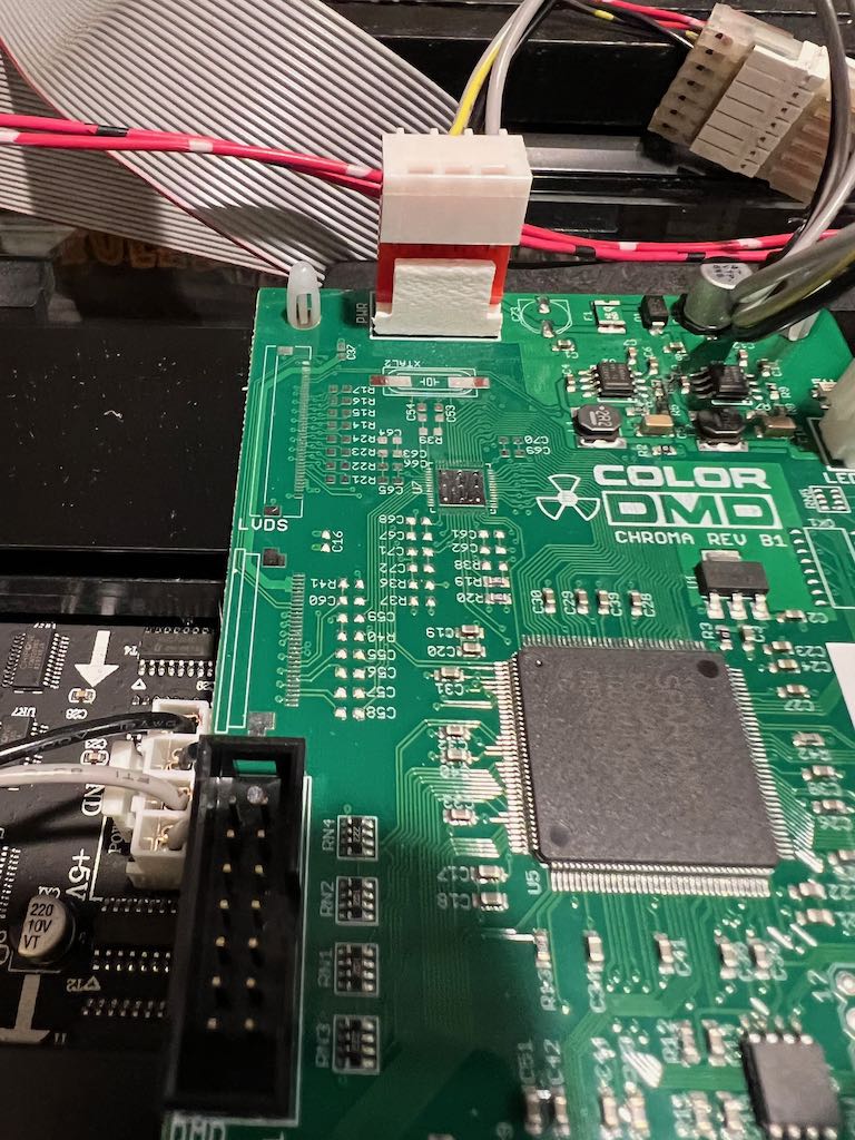
Now we need to reconnect the 2 cables that were removed from the DMD logic board earlier. This is the larger ribbon cable from CN3 and the small 3-pin power cable from CN2. The picture below shows all of these cables connected. CN3 is on the bottom left and CN2 is on the upper right.
Finally, using the new ribbon cable included with the ColorDMD LED kit, connect the DMD logic board (at CN1) to the ColorDMD LED board (labeled "DMD"). Make sure the red side of the cable has the same orientation as shown in the picture!
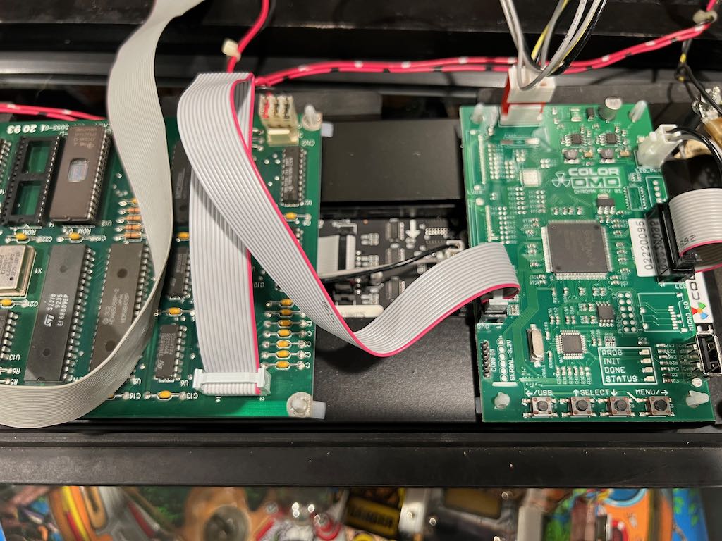
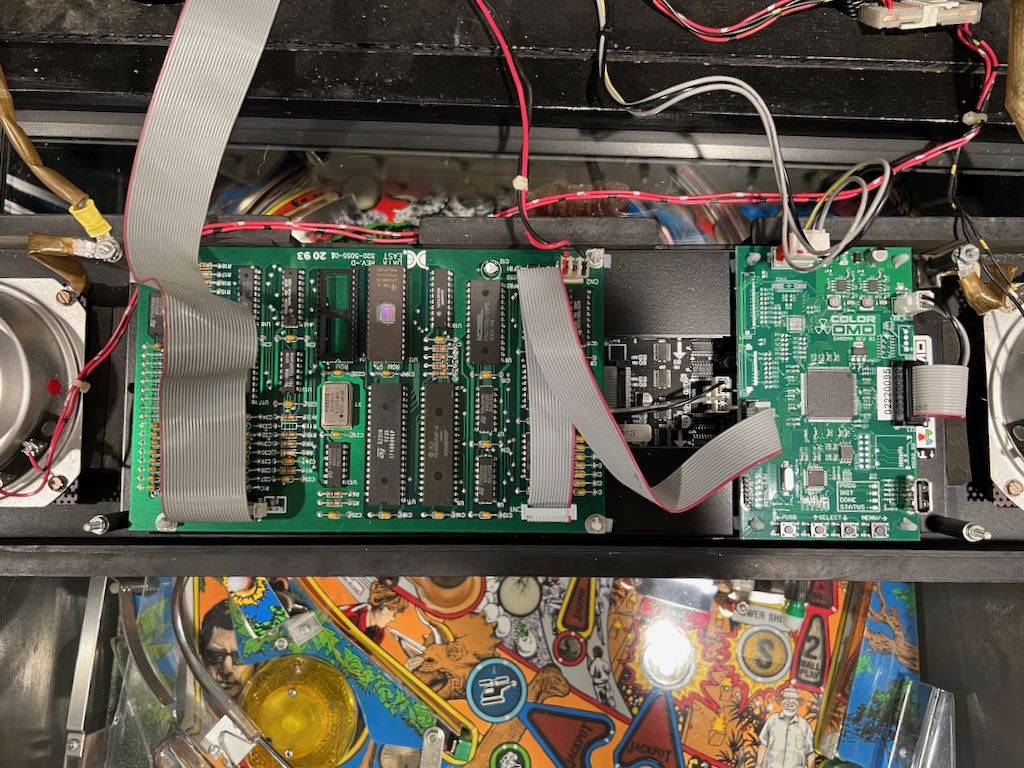
Here's a picture of the completed speaker panel with LED ColorDMD.
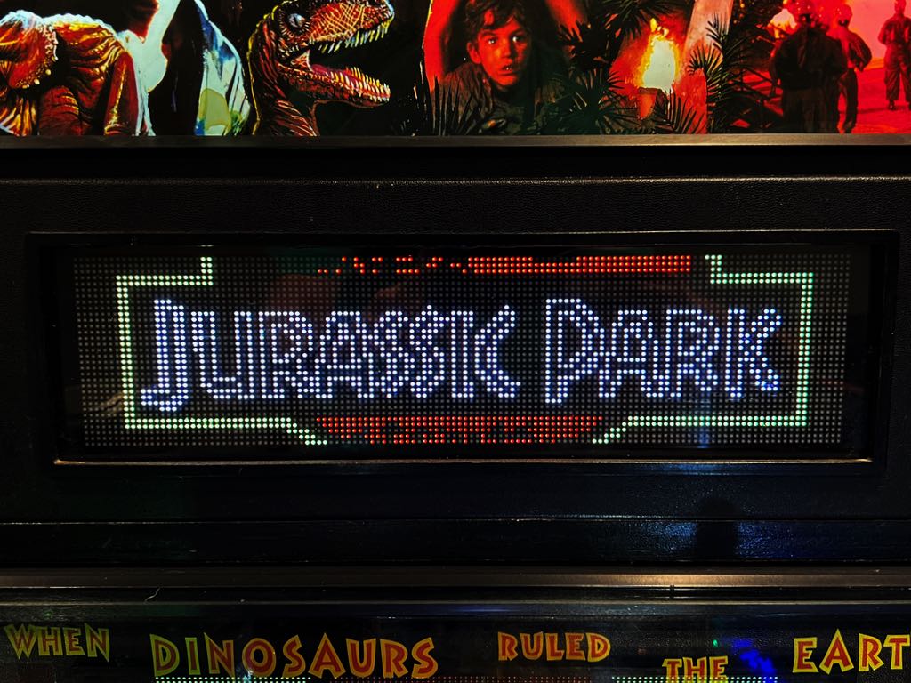
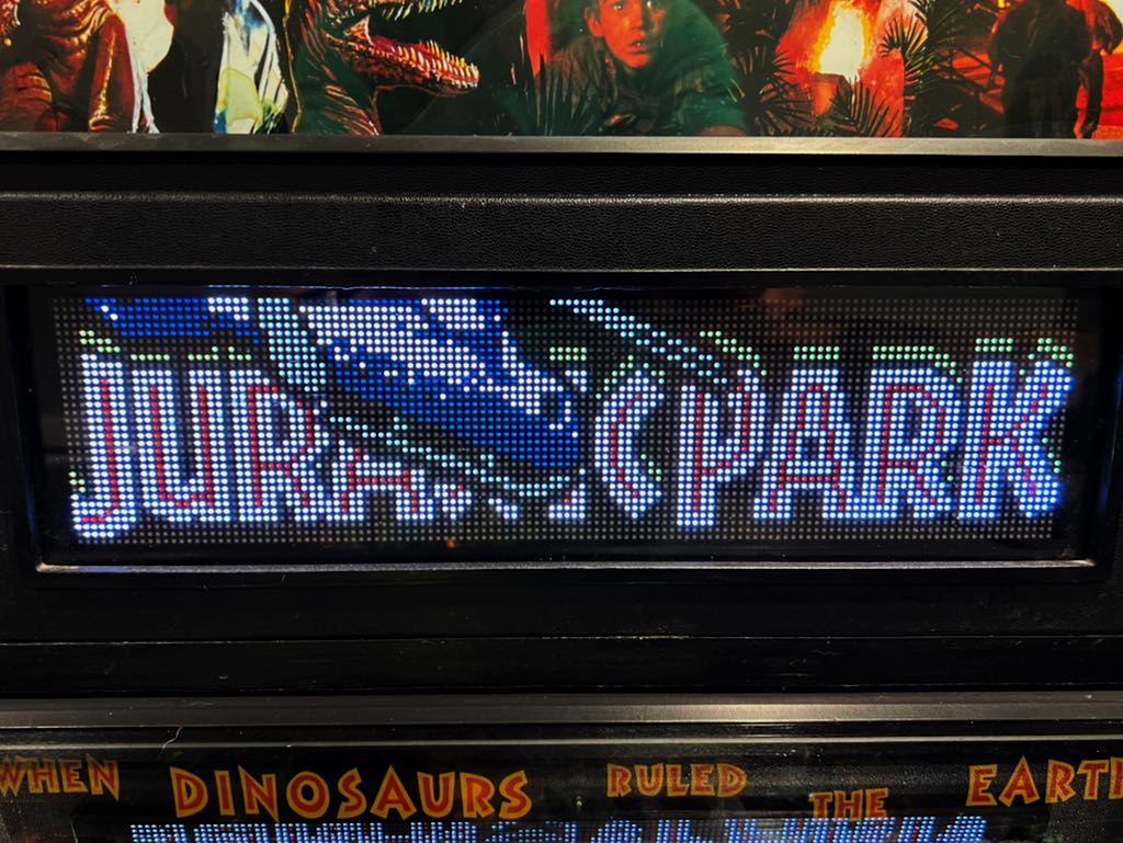
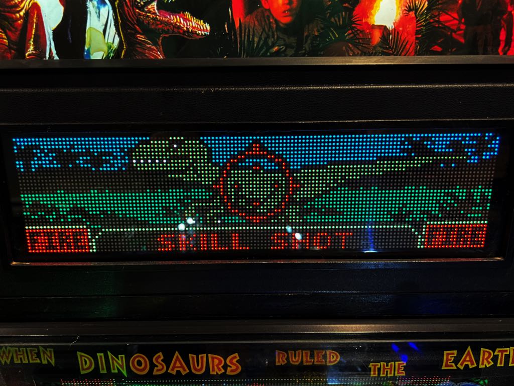
Below are examples of the display after using a USB thumb drive and downloading the ColorDMD Jurassic Park firmware.

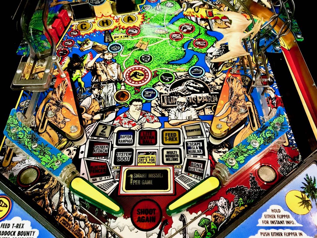
Results after "Shopping" the Playfield
March 24, 2018
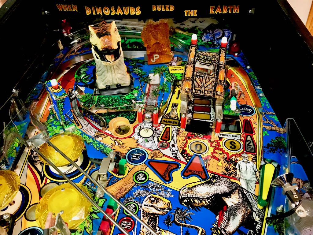
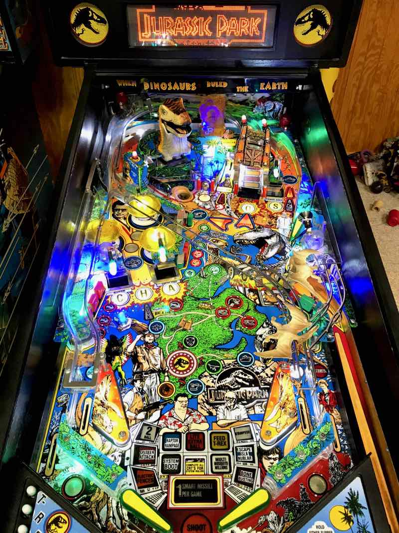
All the other entries on this page discuss the various repairs I've done. This section shows how nicely Jurassic Park cleaned up. As I write this, Jurassic Park is operating at 100% and has been "dialed in" so it plays very well. I'd say I'm about 95% done shopping the upper playfield. The pictures below show how it looks so far...

General Illumination Bulb was not Working
March 26, 2018
Jurassic Park has a square box to the left of the T-Rex. This box has the image of a T-Rex, a lamp matrix controlled lamp on the top, a flasher inside, and a spotlight connected to the GI (general illumination). This GI spotlight didn't work.
I tried replacing the bulb with another #555, but that made no difference. I measured the voltage on the socket and was perplexed when the reading was about 1.5V AC. That's not a valid voltage at all, yet it's not zero volts either. I took off the plastics around the T-Rex box to get a closer look at the wiring. I was taken back when I saw a previous owner placed the wiring on the OUTSIDE of the rubber. The ball was actually hitting these wires during gameplay (although I had never noticed).
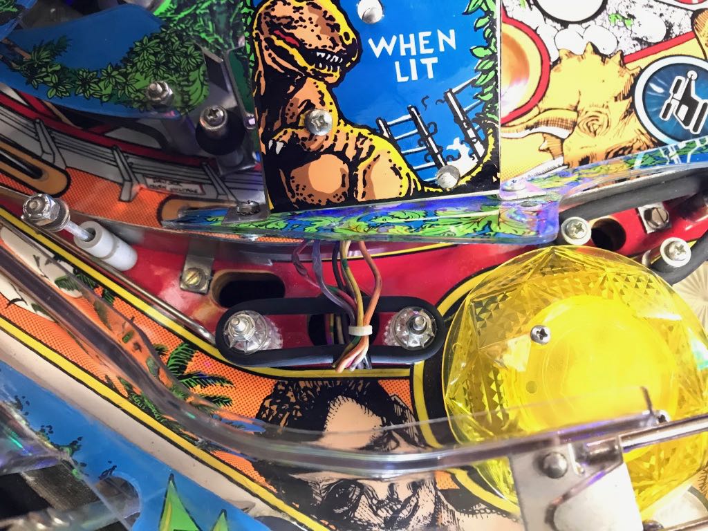
If you look closely at the picture above, you can see the two wires on the left are severely "flattened" as if they had been crushed. I wasn't sure if the wire inside the insulation had been damaged, perhaps increasing the resistance and lowering the voltage. I decided to cut out of bad sections and splice back together. Unfortunately, I didn't take a picture of the spliced wire (it looks nice, I used shrink-wrap). Even more unfortunately, this repair had no impact to the strange 1.5V AC and the GI lamp still didn't work.
I looked further and found what turned out to be the root cause. One of the previous owners had mis-wired the GI lamp and the matrix lamp! There was a sign all along that I missed. The matrix lamp was never solid. Rather, when the lamp matrix told the lamp to turn on, it always blinked. I thought this was a nice effect and assumed that either the game was doing this intentionally or a previous owner had put a blinking bulb in there. No... This was because it was wired wrong.
It turns out 50% of the wiring was right (or you could say 50% was wrong). One of the wires that should have gone to the lamp matrix bulb had been wired to the GI and one of the wires that should have gone to the GI went to the lamp matrix. When I fixed this, the GI lamp worked as expected and the lamp matrix lamp was solid when turned on. There was no more flashing. I decided to put a small twisty tie around each pair of wires to (hopefully) prevent someone from wiring them wrong in the future. The correct wiring is shown in the picture below.

Ball Trough Problems
March 19, 2018
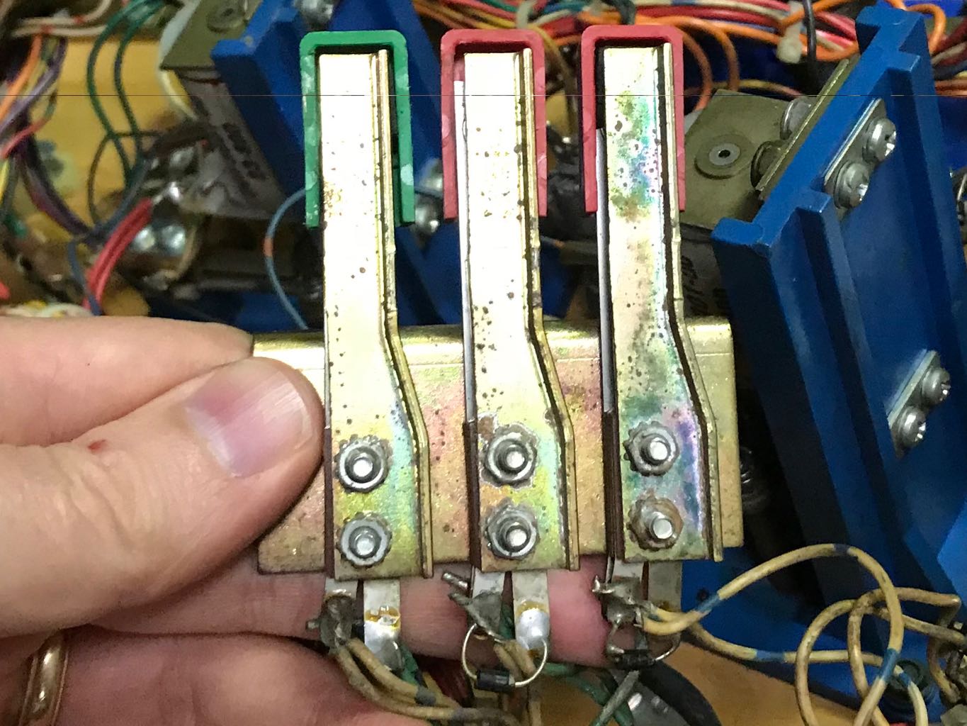
Jurassic Park would play to many balls during multiball and would sometimes lose track how many balls were on the playfield. The first place I started looking, to resolve the problem, was the ball trough. There were at least 3 problems fairly apparent
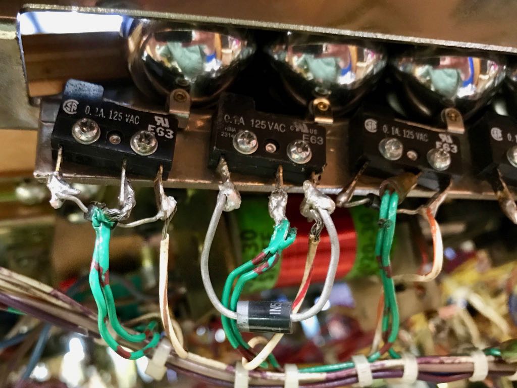
- The diode on one of the switches had broken off (and someone had replaced a diode with an enormously over-sized one)
- Several of the switch activators had been aggressively bent. I suspect a previous owner thought that bending the activator could fix anything ... not that it did
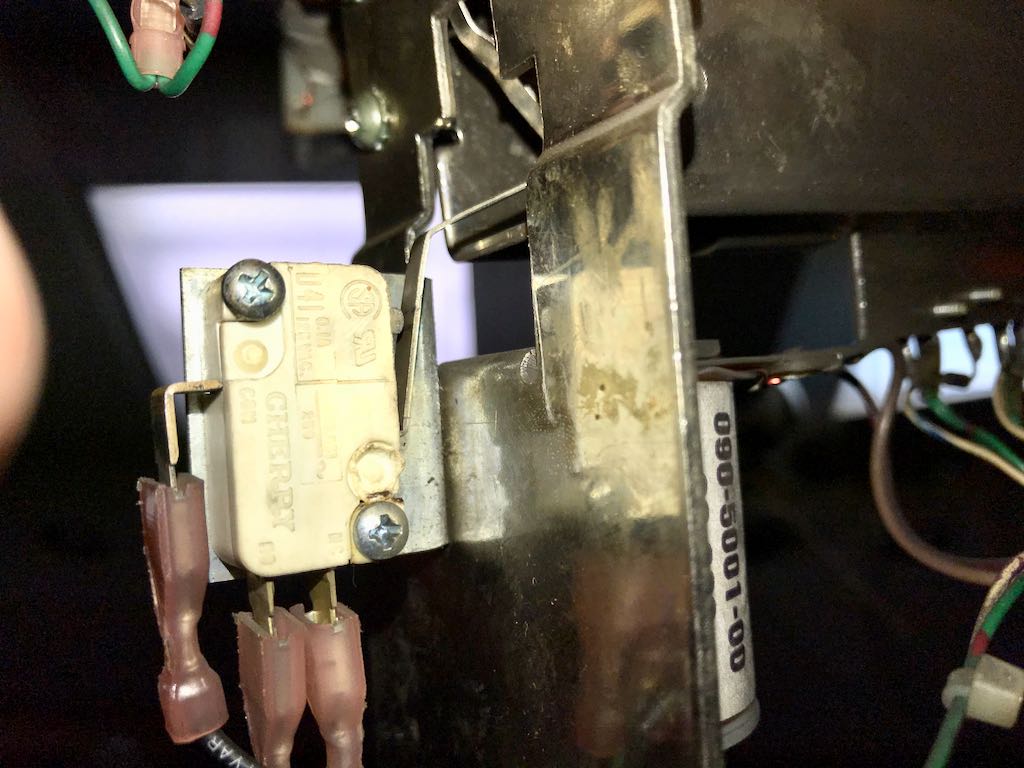
- The 7th switch, all the way at the end of the trough, was worn out (and a previously owner had performed yet more aggressive bending on the activator
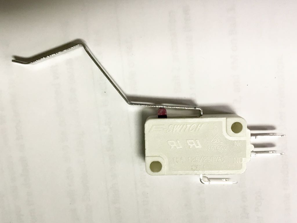
I replaced the diode that had fallen off and replaced the over-sized diode. It took several iterations, but I bent the switch activators back into their normal positions. Finally, I purchased a new microswitch of the 7th switch on the trough and replaced the original. Jurassic Park now gives the correct number of pinballs during multiball and never wants to fire an unwanted ball onto the playfield.
Below is a picture of the original switches (and their unprofessional soldering) along with the giant diode.
Below is the original switch installed on the trough. This is the very end of the through, just underneath the shooter lane. The new switch (not installed) is shown afterwards.
Strange Audio (beeps, buzzing, etc.)
March 21, 2018
When I play tested Jurassic Park before purchasing, the audio worked fine. The music played correctly, the speech comprehensible. As is the case with many pins, when I brought it home, sometime had broken. In this case, it was the audio.
Luckily, it was a quick fix. I reseated the audio ROM on the sound board and the problem went away (and hasn't come back some five months later --- as of this writing)
Speaker Hum / Buzz
February 26, 2018
Data East pinball machines are known for having speaker hum. People often speak generally about the hum from these machines. It is, however, typically generated by 1 of 3 causes.
- Constant Hum / Buzz from Speakers
- Hum / Buzz from the DMD (typically changing volume based on what is displayed)
- Playfield light effects that can be correlated to Hum / Buzz
The hum / buzz from DMD and light effects can be eliminated by (1) disconnecting the power cable that goes to the DMD and (2) entering diagnostic mode. The first, well, disables the DMD from displaying any content. The second places the game into diagnostic mode where it doesn't perform any light shows.
I noticed that the constant hum / buzz was not impacted by the volume setting. Specifically, I could turn the volume up or down and the hum would not get any louder or softer. This strongly suggests the hum / buzz is being introduced after the volume circuity.
Using an app on my phone, I was able to determine that the major hum / buzz cause was a 120 Hz sound at about 58 dB. Using a scope, I could see this in the 12 VDC signal going to the sound board. With my XPIN DE5047 after market power board, I measured a 1.3 VAC 120 Hz ripple on the DC line.
A 120 Hz ripple is a signature of a full wave bridge rectifier. Briefly, a full wave bridge rectifier takes a 60 Hz AC source (at least in North America) and converts it to DC. The negative portion of the 60 Hz wave form is made "positive", resulting in a 2x frequency change. Hence, 60 Hz becomes 120 Hz. This ripple is typically reduced by the use of a smoothing capacitor.
The XPIN DE5047 has a 10,000 uF cap. The original Data East power board using 18,000 uF cap. To see if this was part of the problem, I added 15,000 uF in parallel to the existing 10,000 uF. With this configuration, the ripple was reduced to about 500 mV. However, the audio hum / buzz wasn't significantly impacted. I added additional capacitance but was never able to get the ripple any lower. I still don't completely understand this observed behavior. One theory is that the power board cannot provide enough current to charge my caps fast enough and, as a result, they cannot smooth ripple further. That's just a theory.
I also replaced several caps on the sound board. It's not uncommon for caps to behave poorly with age. I replaced C31 / C52 (with upgraded 1000 uF) and C60 / C67 / C74 (with 470 uF). This had no impact ... or, perhaps, seemed to make the hum a little worse!
I had read that some people had good results by powering the sound board with an external power supply. While I feel this is a bit of a hack, I decided to give it a try. If nothing else, it would let me know whether the sound board was capable of producing audio without hum. I did the following:
- Purchased a $15 ATX power supply
- Using the +5 VDC, +12VDC, -12VDC and ground from the ATX, built a cable that connects to the sound board's 6 pin connector
- Connected the ATX Power On wire to Ground, ensuring the ATX provides power immediately when AC power is available
- Wired the ATX power supply into the 120 VAC switched line that is used for a dollar bill validator
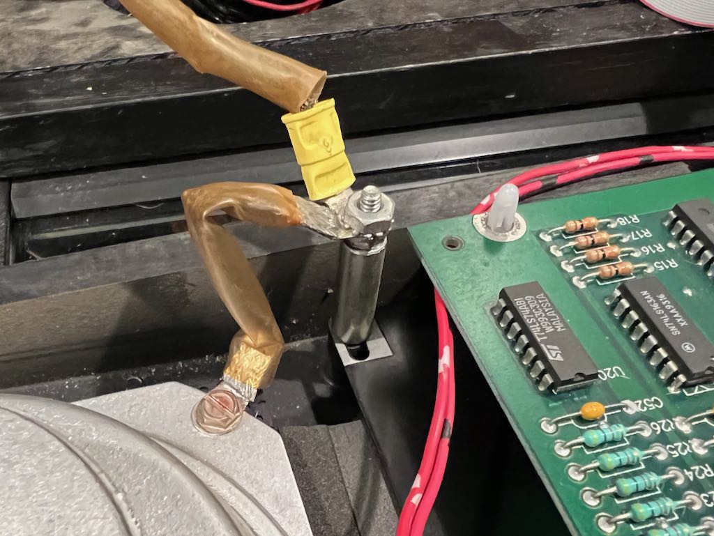
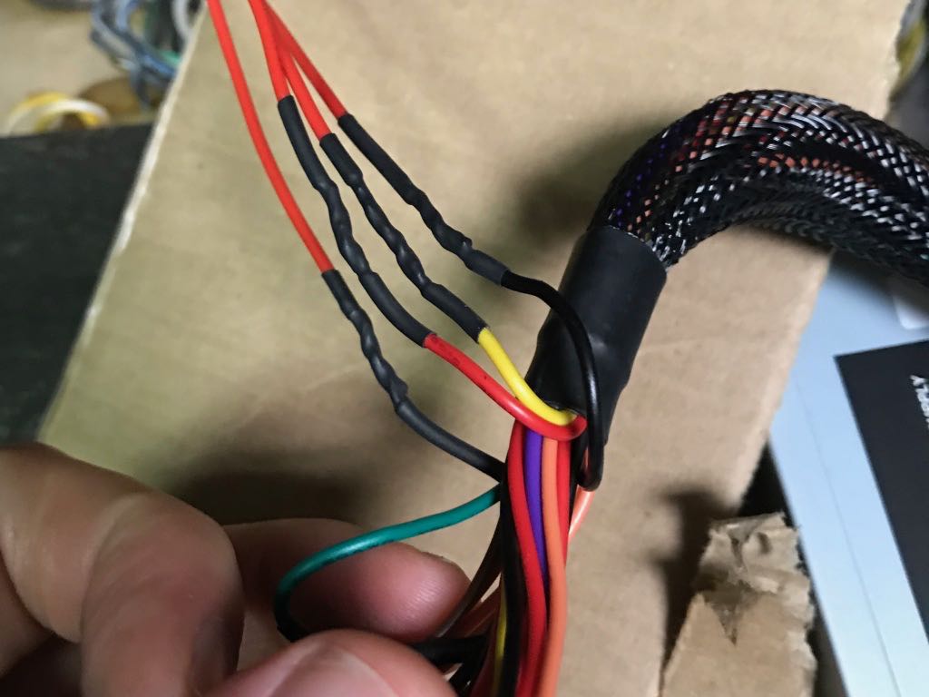
The picture below shows the wire splices done to the ATX power output. I only had red wire so, unfortunately, all 4 wires are red.
This picture below shows the splice between the Data East 120 VAC lines and the ATX power cable. The "service" plug on the Data East pinball cannot be used because it isn't switched on and off along with the game. Rather, it provides power all the time.

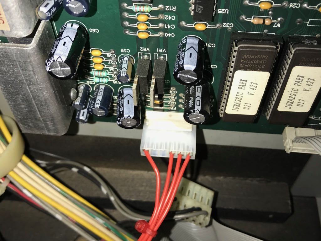
This picture below shows the connector that was built and plugs into the sound board's power input.
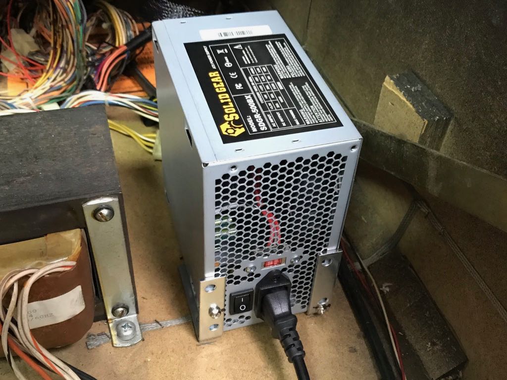
Finally, the image below shows that ATX power supply. I drilled 2 holes into metal L-brackets at the right position to allow screws to hold the ATX supply in place. The ATX supply is also connected to the ground braid.
In conclusion, I feel using an external power supply is a bit of a hack. However, as far as hacks go, I feel I've performed this one in a fairly professional manner. I'm still interested in resolving the hum without an external power supply, but this approach will hold me over until I decide to peruse the analysis further.
Flipper Adjustment
March 19, 2018
Bally/Williams Pinball machines from (at least) the 1990s had 2 small holes in the playfield that could be used to ensure the flipper resting position is correct. The technician would place a toothpick in the hole and then let the bottom of the flipper rest on the toothpick. Very simple.
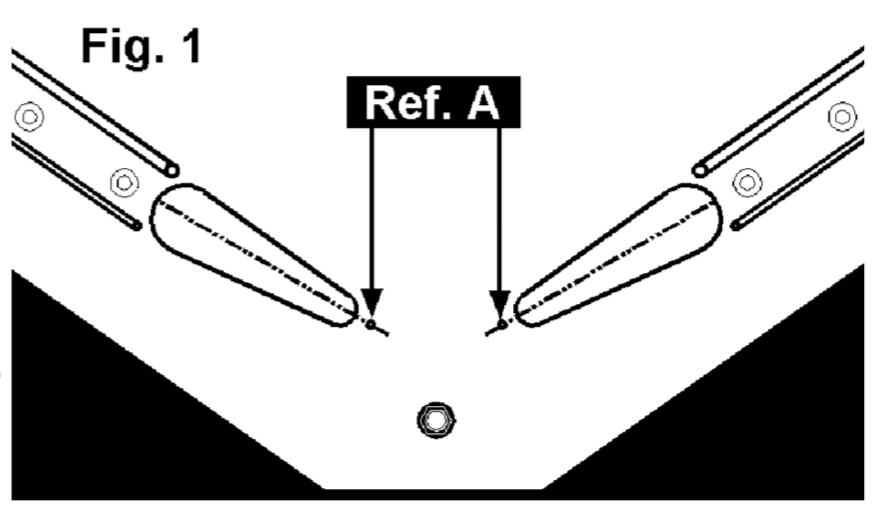
Data East also placed 2 small holes in the playfield, but not in a position where a toothpick could be used (at least starting with Lethal Weapon). Rather, the technical needed to "eyeball" the center of the flipper to the hole. It's not too uncommon to see Data East pins with flippers aligned incorrectly. The wrong alignment has a significant impact on the gameplay.
Service Bulletin 108 describes the proper alignment. The key figure is captured and shown below. Oh, I'm writing all this because the flippers on my Jurassic Park were not aligned correctly and the game played significantly better once the alignment was corrected.
Subway Cleaning
March 5, 2018
It had clearly been a very long time since anyone took Jurassic Park's subway off the bottom of the playfield and cleaned it. Below is the before (dirty) picture and the after (clean) picture.
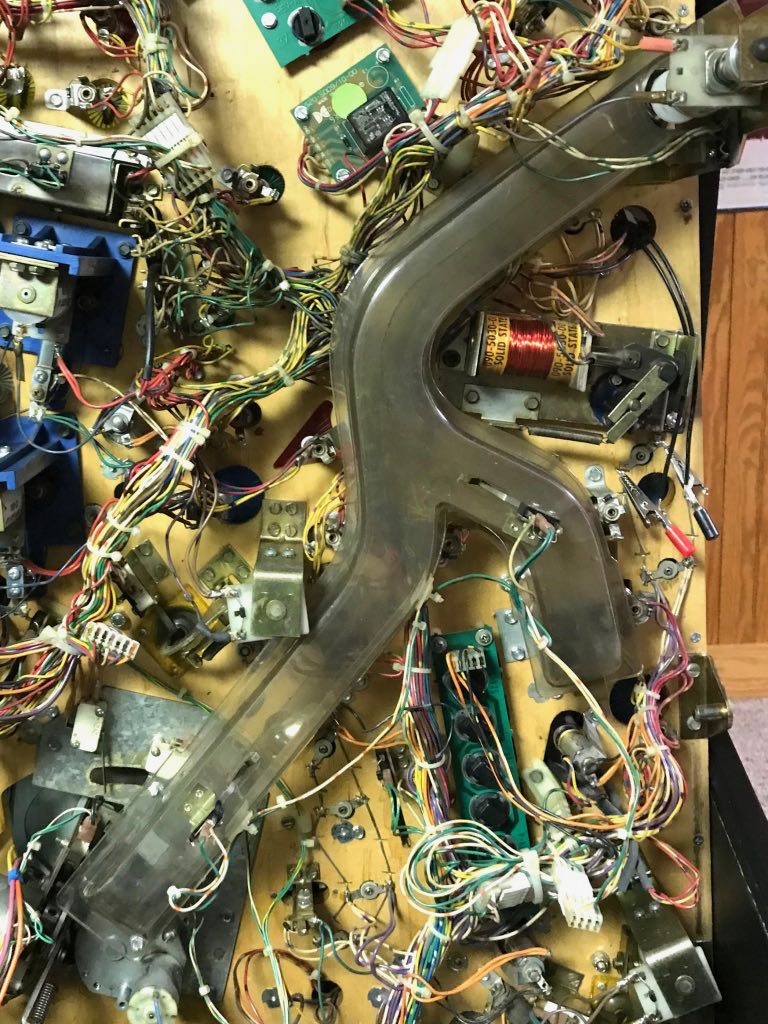
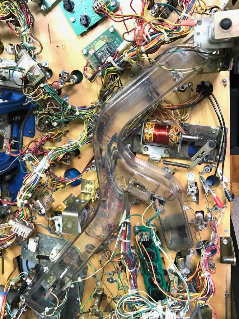
Removing the subway is very easy. There are only a few screws and then a connector, which allows the switches on the subway to be detached from the wiring harness.
Randomly Weak Right Flipper
March 19, 2018
The right flipper on my Jurassic Park would randomly be weak. When this occurred, the flipper would only "lightly" hit the pinball up the playfield. It never happened multiple times in a row and I could never notice any pattern (such as how long I'd been playing). I took the flipper mechanism apart, everything looked good. I replaced the nyliner, but after reassembly found the flipper would occasionally still be weak.
I figured out the problem was with the flipper's end-of-stroke leaf switch. Data East's Jurassic Park pinball has an end-of-stroke switch (EOS) that detects when the flipper is fully extended. This switch is CLOSED when the flipper is at rest and only becomes open when the flipper is fully extended. If the contacts of the EOS switch are dirty, the switch can read OPEN even when the flipper is not fully extended.
Below is a picture of the flipper's end-of-strike switch.
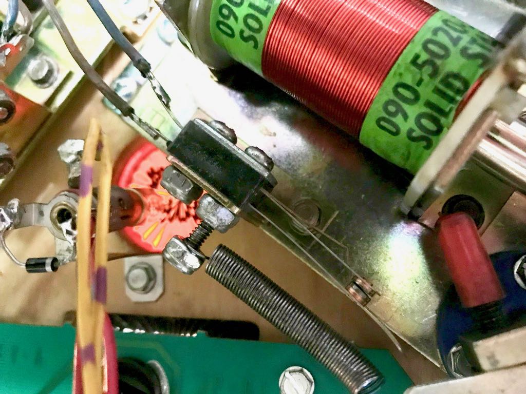
Using my DMM and leads clipped to the ends of the leaf switch, the problem was easy to see. Set for Ohm mode, I could see the reading moving from 0 or 5 Ohms then bounce up to 200 or even 800 Ohms --- all without wiggling the leaf switch. I did the classic "clean the switch contacts with a business card" and the problem hasn't been seen since.
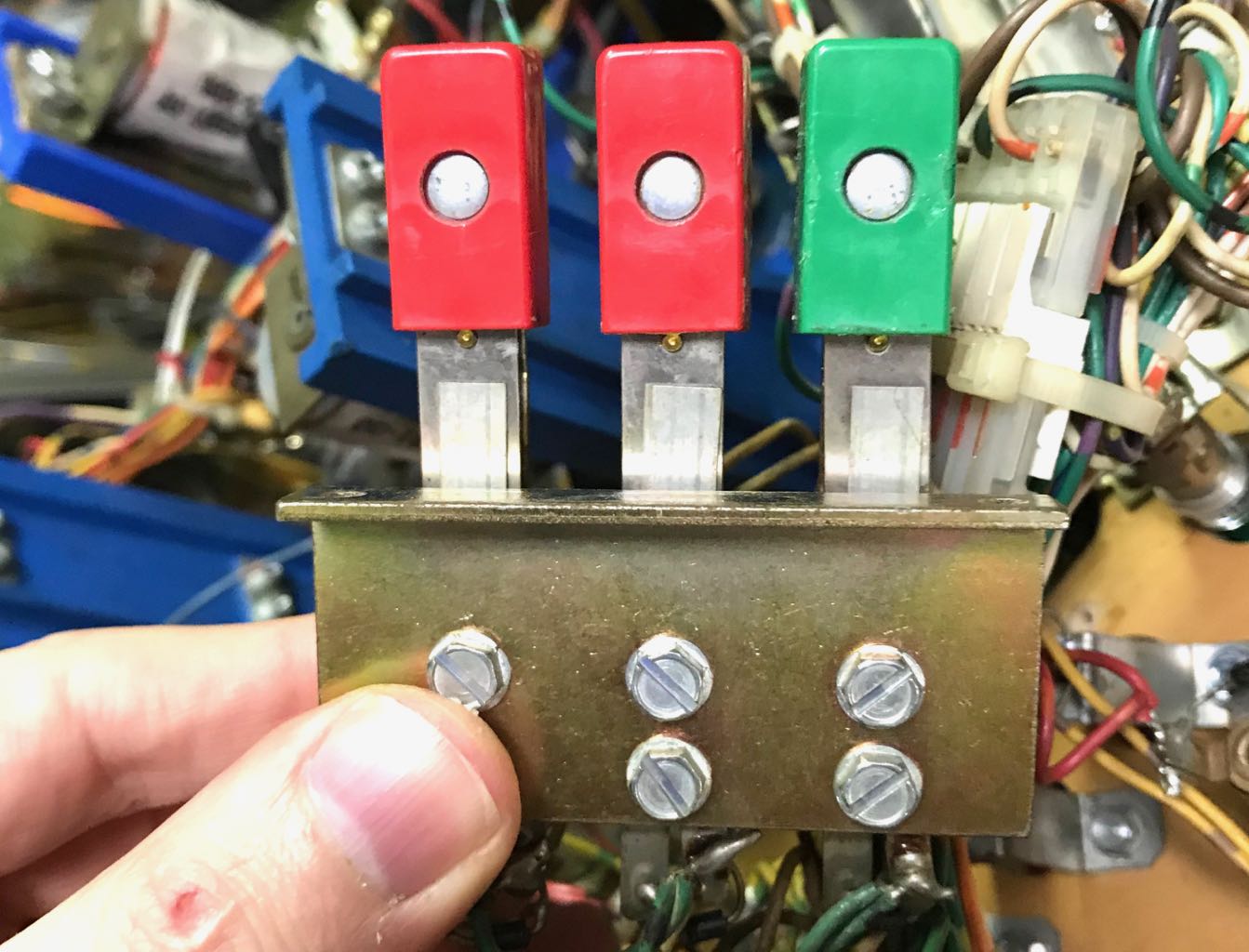
3-Bank Target
March 19, 2018
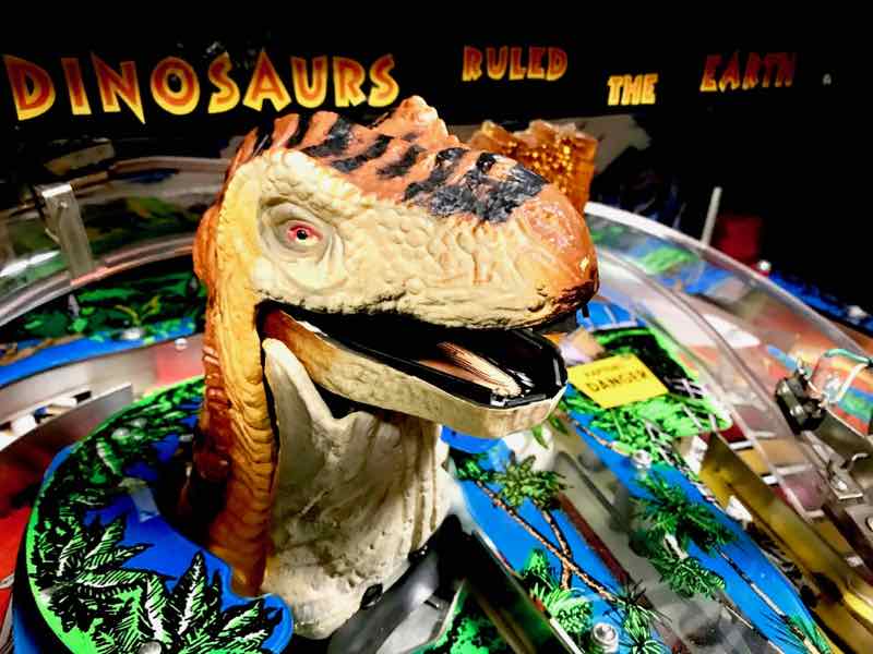
T-Rex
One of the best "toys" in pinball? A dinosaur that eats a pinball? Yes, I think so.
Rottendog DPS004 Doesn't Play Nice with DMD
March 19, 2018
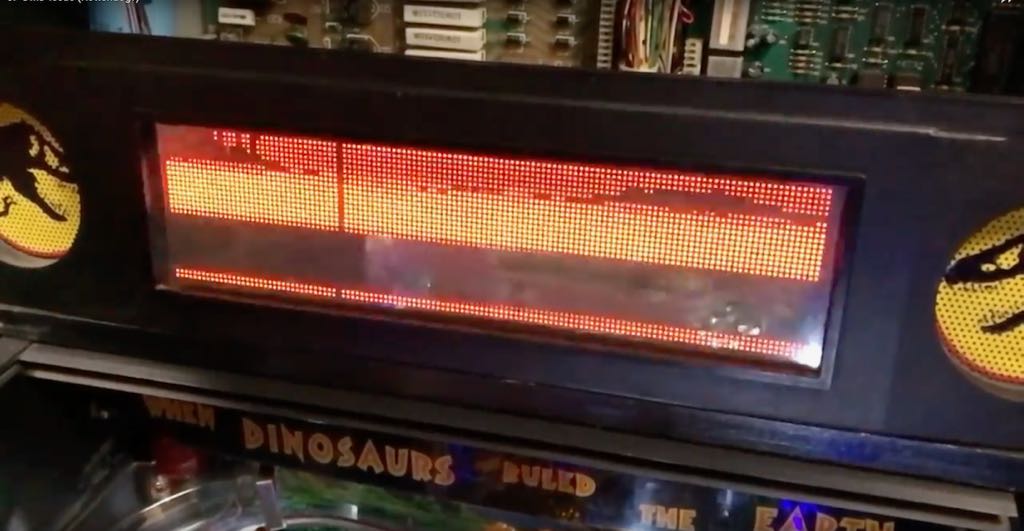
Unfortunately my Jurassic Park came with an aftermarket power board. It was the Rottendog DPS004 version. This Rottendog DPS004 didn't play well with my DMD. When the DMD had most of the individual "dots" activated, the DMD would go crazy. It would be unable to keep the dots on, creating a flickering mess.
I did a fair amount of research into this problem and I'm not the only one who has experienced the Rottendog DPS004 failing to display images properly on the DMD. There have been repeats for years and years.
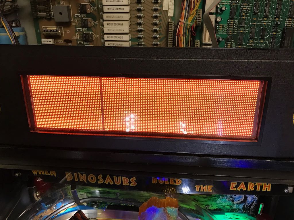
While debugging this problem, I put the DMD into a Bally/Williams pinball machine and it performed flawlessly, whether having just a few dots active or having all the dots active. Below is a picture of the problem caused by using the Rottendog DPS004 with my DMD. This is a picture of the diagnostic where the entire DMD should be active except for a line column. You can see the column about 1/3 of the way across. While this is just a single still image, imagine all the other dots 'rolling' and turning on and off.
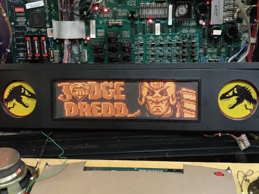
Below is a picture of the DMD from Jurassic Park installed into a Judge Dredd machine. As you can see, the DMD worked just fine.
The nicest thing I can say about the Rottndog DPS004 is that it has trouble driving some older DMDs. I ended up purchasing an XPin XP-DE5047 power board and it drives the DMD correctly. Below is a picture of the same diagnostic that caused the Rottendog DPS004 is display garbage (but now working fine with XPin).
Playfield
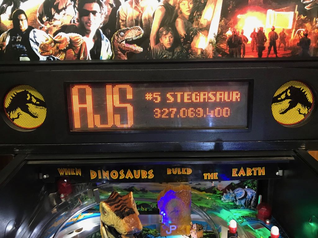
Oh no! Spelling Error...
March 21, 2018
"Stegasaur" isn't right. I suspect it should "Stegosaurus"...